Experiments- 11
Verify the truth table of one bit and two-bit comparator using logic gates.
Introduction
A magnitude digital comparator is a combinational circuit that compares two digital or binary numbers in order to find out whether one binary number is equal, less than or greater than the other binary number. We logically design a circuit for which we will have two inputs one for A and other for B and have three output terminals, one for A > B condition, one for A = B condition and one for A < B condition.
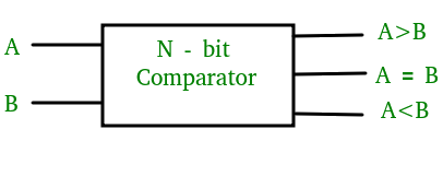
Figure-1: Block Diagram of Comparator
1) 1-Bit Magnitude Comparator :
A comparator used to compare two bits is called a single bit comparator. It consists of two inputs each for two single bit numbers and three outputs to generate less than, equal to and greater than between two binary numbers. The truth table for a 1-bit comparator is given below :
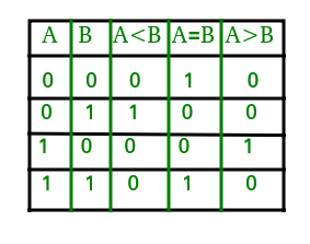
Figure-2: Truth Table of 1-Bit Comparator
From the above truth table logical expressions for each output can be expressed as follows:
A > B: AB'
A < B: A'B
A = B : A'B' + AB
By using these Boolean expressions, we can implement a logic circuit for this comparator as given below :
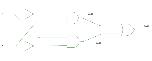
Figure-3: Logic Circuit of 1-Bit Comparator
Simulator 1:
- Step-1) Switch ON the power supply button to supply 5V to the circuit.
- Step-2) Press Switch 1 for input A and Switch 2 for input B. The switch in ON state is
 and the switch in OFF state is
- Step-3) i)When the input A is greater than the input B,LED 1 lits up.
- ii)When the input A is lesser than the input B, LED 2 lits up.
- iii)When the input A is equal to the input B, LED 3 lits up.
- The LED in OFF state is
 and the LED in ON state is
  .
. - Step-4) Click on "Add" Button to add data to the Truth Table.
- Step-5) Repeat Steps 2 to 4 for another set of data.
- Step-6) Click "Print" to get the printout of the Truth Table.
Simulator 2:
- Step-1) Enter the Boolean input "A" and "B".
- Step-2) Enter the Boolean output for your corresponding inputs.
- Step-3) Click on "Check" Button to verify your output.
- Step-4) Click "Print" if you want to get print out of Truth Table.
LAB Simulation
2) 2-Bit Magnitude Comparator :
A comparator used to compare two binary numbers each of two bits is called a 2-bit magnitude comparator. It consists of four inputs and three outputs to generate less than, equal to and greater than between two binary numbers.
The truth table for a 2-bit comparator is given below:
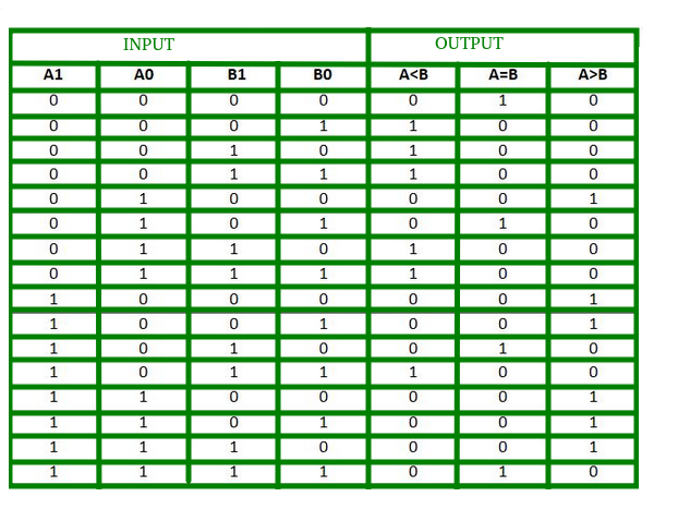
Figure-4: Truth Table of 2-Bit Comparator
From the above truth table logical expressions for each output can be expressed as follows:
A > B : A1B1’ + A0B1’B0’ + A1A0B0’
A = B : A1’A0’B1’B0’ + A1’A0B1’B0 + A1A0B1B0 + A1A0’B1B0’
: A1’B1’ (A0’B0’ + A0B0) + A1B1 (A0B0 + A0’B0’)
: (A0B0 + A0’B0’) (A1B1 + A1’B1’)
: (A0 Ex-Nor B0) (A1 Ex-Nor B1)
A < B : A1’B1 + A0’B1B0 + A1’A0’B0
By using these Boolean expressions, we can implement a logic circuit for this comparator as given below :
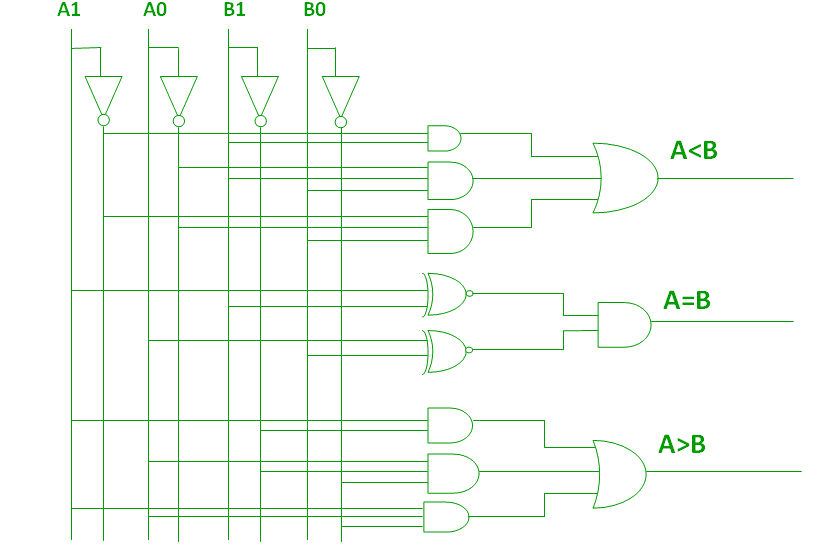
Figure-5: Logic Circuit of 2-Bit Comparator
Applications of Comparators:
- Comparators are used in central processing units (CPUs) and microcontrollers (MCUs).
- These are used in control applications in which the binary numbers representing physical variables such as temperature, position, etc. are compared with a reference value.
- Comparators are also used as process controllers and for Servo motor control.
- Used in password verification and biometric applications.
Simulator 1:
- Step-1) Switch ON the power supply button to supply 5V to the circuit.
- Step-2) Press Switch 1 for input A1,Switch 2 for input A0,Switch 3 for input B1and Switch 4 for input B0. The switch in ON state is and the switch in OFF state is
- Step-3) i)When the input A1A0 is greater than the input B1B0,LED 1 lits up.
- ii)When the input A1A0 is lesser than the input B1B0,LED 2 lits up.
- iii)When the input XA1A0 is equal to the input B1B0,LED 3 lits up.
- The LED in OFF state is and the LED in ON state is .
- Step-4) Click on "Add" Button to add data to the Truth Table.
- Step-5) Repeat Steps 2 to 4 for another set of data.
- Step-6) Click "Print" to get the print out of the Truth Table.
Simulator 2:
- Step-1) Enter the two bit Boolean input "A" and "B".
- Step-2) Inputs should be written such that for 'A'="A1A0" and for 'B'="B1B0"
- Step-3) Enter the Boolean output for your corresponding inputs.
- Step-4) Click on "Check" Button to verify your output.
- Step-5) Click "Print" if you want to get print out of Truth Table.
LAB Simulation
TEST
References
- William Gothmann H, Digital Electronics : An Introduction To Theory And Practice , Prentice Hall, 2nd ed. 1982
- M. Morris Mano, Michael D Ciletti, "Digital Design", Pearson, 4th ed. 2008
- Thomas L. Floyd, R. P. Jain, "Digital Fundamentals", Pearson, 11th ed. 2017
- S Salivahanan, S Arivazhagan, "Digital Circuits and Design", Vikas Publishing House Pvt Ltd., 3rd ed. 2009
- Ronald J. Tocci, Neal S. Widmer, Gregory L. Moss, "Digital Systems", Pearson, 10th ed. 2009
- Anil K. Maini, "Digital Electronics: Principles, Devices and Applications", Wiley-Blackwell, 2007
- 1 Bit comparator: https://www.youtube.com/watch?v=UO-K0Jx2Hs0
- Magnitude Comparator: https://www.geeksforgeeks.org/magnitude-comparator/
- Digital Comparator and Magnitude Comparator: https://www.electronicshub.org/digital-comparator-and-magnitude-comparator/


Comments
Post a Comment