Experiments-4
To Study & Verify Half and Full Subtractor
Introduction
Subtractor circuits take two binary numbers as input and subtract one binary number input from the other binary number input. Similar to adders, it gives out two outputs, difference and borrow (carry-in the case of Adder). There are two types of subtractors.
- Half Subtractor
- Full Subtractor
1) Half Subtractor
The half-subtractor is a combinational circuit which is used to perform subtraction of two bits. It has two inputs, A (minuend) and B (subtrahend) and two outputs Difference and Borrow. The logic symbol and truth table are shown below.
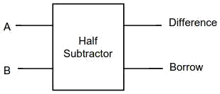
Figure-1:Logic Symbol of Half subtractor
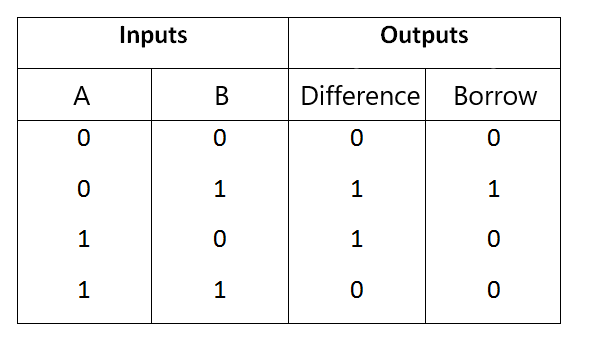
Figure-2:Truth Table of Half subtractor
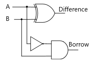
Figure-3:Circuit Diagram of Half subtractor
From the above truth table we can find the boolean expression.
Borrow = A' B
From the equation we can draw the half-subtractor circuit as shown in the figure 3.
Simulator 1:
- Step-1) Connect the Supply(+5V)
 to the circuit.
 - Step-2) First press "ADD" button to add basic state of your output in the given table.
- Step-3) Press the switches to select the required inputs "A" and "B".
- Step-4) Press "ADD" button to add your inputs and outputs in the given table.
- Step-5) Repeat steps 3&4 for next state of inputs and their corresponding outputs.
- Step-6) Press the "PRINT" button after completing your simulation to get your results.
Simulator 2:
- Step-1) Enter the Boolean input "A" and "B".
- Step-2) Enter the Boolean output for your corresponding inputs.
- Step-3) Click on "Check" Button to verify your output.
- Step-4) Click "Print" if you want to get print out of Truth Table.
- Step-5) Click "Reset" if you want to reset inputs and outputs.
LAB Simulation
Half Subtractor
2) Full Subtractor
A full subtractor is a combinational circuit that performs subtraction involving three bits, namely A (minuend), B (subtrahend), and Bin (borrow-in) . It accepts three inputs: A (minuend), B (subtrahend) and a Bin (borrow bit) and it produces two outputs: D (difference) and Bout (borrow out). The logic symbol and truth table are shown below.

Figure-4:Logic Symbol of Full subtractor
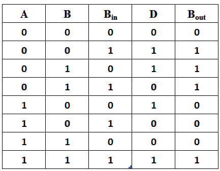
Figure-5:Truth Table of Full subtractor
From the above truth table we can find the boolean expression.
Bout = A' Bin + A' B + B Bin
From the equation we can draw the Full-subtractor circuit as shown in the figure 6.

Figure-6:Circuit Diagram of Full subtractor
Simulator 1:
- Step-1) Connect the Supply(+5V) to the circuit.
- Step-2) First press "ADD" button to add basic state of your output in the given table.
- Step-3) Press the switches to select the required inputs "A" and "B" and "Bin".
- Step-4) Press "ADD" button to add your inputs and outputs in the given table.
- Step-5) Repeat steps 3&4 for next state of inputs and their corresponding outputs.
- Step-6) Press the "PRINT" button after completing your simulation to get your results.
Simulator 2:
- Step-1) Enter the Boolean inputs "A" and "B" and "Bin".
- Step-2) Enter the Boolean output for your corresponding inputs.
- Step-3) Click on "Check" Button to verify your output.
- Step-4) Click "Print" if you want to get print out of Truth Table.
- Step-5) Click "Reset" if you want to reset inputs and outputs.
LAB Simulation
Test
References
- William Gothmann H, Digital Electronics : An Introduction To Theory And Practice , Prentice Hall, 2nd ed. 1982
- M. Morris Mano, Michael D Ciletti, "Digital Design", Pearson, 4th ed. 2008
- Thomas L. Floyd, R. P. Jain, "Digital Fundamentals", Pearson, 11th ed. 2017
- S Salivahanan, S Arivazhagan, "Digital Circuits and Design", Vikas Publishing House Pvt Ltd., 3rd ed. 2009
- Ronald J. Tocci, Neal S. Widmer, Gregory L. Moss, "Digital Systems", Pearson, 10th ed. 2009
- Anil K. Maini, "Digital Electronics: Principles, Devices and Applications", Wiley-Blackwell, 2007
- Half Subtractor on breadboard: https://www.youtube.com/watch?v=KxfPeGctfnY
- Full subtractor on breadboard: https://www.youtube.com/watch?v=KwG6t0sSajs
- Full Subtractor: https://www.geeksforgeeks.org/digital-logic-full-subtractor/
- Binary Subtractor: https://www.electronics-tutorials.ws/combination/binary-subtractor.html


Comments
Post a Comment