Experiments- 6 (Part -2)
Implementation and verification of decoder/de-multiplexer and encoder using logic gates.
Introduction
Binary code of N digits can be used to store 2N distinct elements of coded information. This is what encoders and decoders are used for. Encoders convert 2N lines of input into a code of N bits and Decoders decode the N bits into 2N lines.
1) 2x4 Decoder / De-multiplexer
The name “Decoder” means to translate or decode coded information from one format into another, so a digital decoder transforms a set of digital input signals into an equivalent decimal code at its output
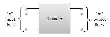
A decoder is a combinational circuit that converts binary information from n input lines to a maximum of m=2^n unique output lines.
1.1) 2-to-4 Binary Decoder
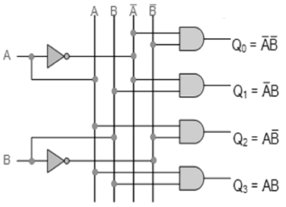
The 2-to-4 line binary decoder depicted above consists of an array of four AND gates. The 2 binary inputs labelled A and B are decoded into one of 4 outputs, hence the description of the 2-to-4 binary decoder. Each output represents one of the minterms of the 2 input variables, (each output = a minterm).
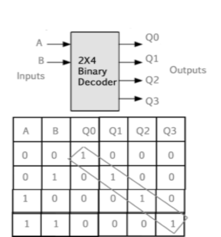
The binary inputs A and B determine which output line from Q0 to Q3 is “HIGH” at logic level “1” while the remaining outputs are held “LOW” at logic “0” so only one output can be active (HIGH) at any one time.
Therefore, whichever output line is “HIGH” identifies the binary code present at the input, in other words it “decodes” the binary input.Some binary decoders have an additional input pin labelled “Enable” that controls the outputs from the device.
This extra input allows the decoders outputs to be turned “ON” or “OFF” as required. Output is only generated when the Enable input has value 1; otherwise, all outputs are 0. Only a small change in the implementation is required: the Enable input is fed into the AND gates which produce the outputs.
If Enable is 0, all AND gates are supplied with one of the inputs as 0 and hence no output is produced. When Enable is 1, the AND gates get one of the inputs as 1, and now the output depends upon the remaining inputs. Hence the output of the decoder is dependent on whether the Enable is high or low.
Simulator :
- Step-1) Connect the supply(+5V)
 to the circuit.
 - Step-2) First press "ADD" button to add basic state of your output in the given table.
- Step-3) Press the switches to select the required inputs named "A" and "B". Also check their corresponding outputs named "Q0" and "Q1" and "Q2" and "Q3".
- Step-4) Press "ADD" button to add your inputs and outputs in the given table.
- Step-5) Repeat step 3 & step 4 for next state of inputs and their corresponding outputs.
- Step-6) Press the "PRINT" button after completing your simulation to get your results.
LAB Simulation
Decoder
2) Encoder
An Encoder is a combinational circuit that performs the reverse operation of Decoder.It has maximum of 2n input lines and ‘n’ output lines, hence it encodes the information from 2n inputs into an n-bit code. It will produce a binary code equivalent to the input, which is active High. Therefore, the encoder encodes 2n input lines with ‘n’ bits.
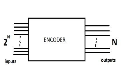
Figure 4. Logic Diagram of ENCODER
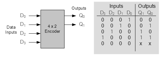
2.1 )4 : 2 Encoder
The 4 to 2 Encoder consists of four inputs Y3, Y2, Y1 & Y0 and two outputs A1 & A0. At any time, only one of these 4 inputs can be ‘1’ in order to get the respective binary code at the output.
Simulator :
- Step-1) Connect the supply(+5V)
 to the circuit.
 - Step-2) First press "ADD" button to add basic state of your output in the given table.
- Step-3) Press the switches to select the required inputs "D0" and "D1" and "D2" and "D3". Also check their corresponding ouyputs named "Q1" and "Q0".
- Step-4) Press "ADD" button to add your inputs and outputs in the given table.
- Step-5) Repeat step 3 & step 4 for next state of inputs and their corresponding outputs.
- Step-6) Press the "PRINT" button after completing your simulation to get your results.


Comments
Post a Comment