BE Lab Manual Experiment 7
Experiment 7
Aim: - To study Half and Full Subtractor Circuit using Logic gates.
Apparatus:-Half Substractor and Full Substractor kit, patch chords, digital multimeter.
Theory:- In a binary system, there are only two numbers, 0 & 1. there are four basic cases of binary subtraction.
For Half Subtractor:-
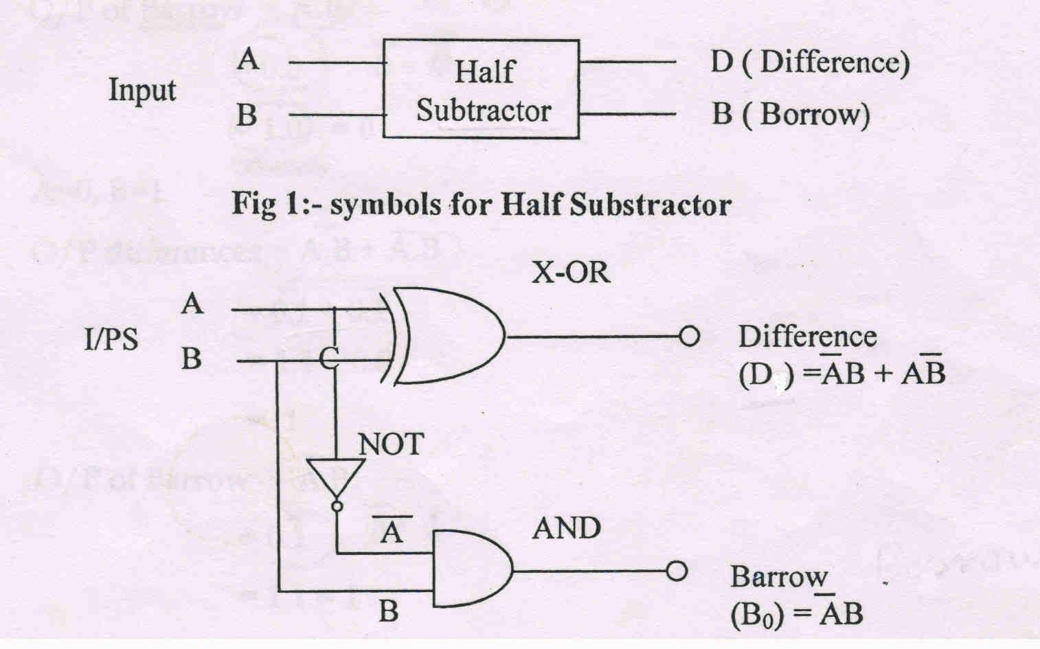
Half Substractor is a logic circuit that performs the Substractor of two binary bits only. It Subtracts the B (Subtrahend) from A (minuend) and generates the difference (D) and borrow (Bo). Figure 1 shows the block systematic of half Subtractor
Truth table:-

Operation:-
The output of the EX-OR gate is called differences while the output of AND gate is the borrow.


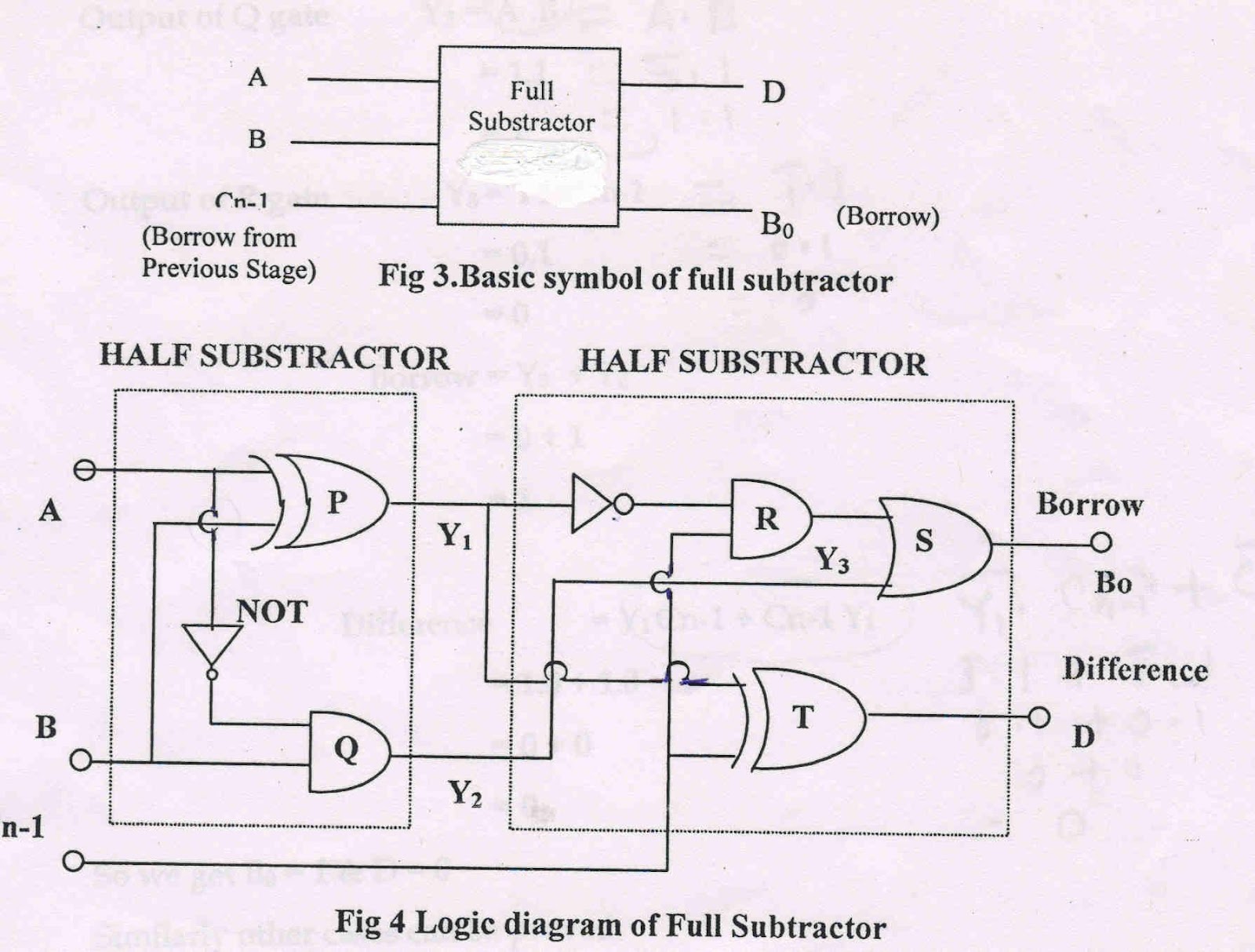
Full Substractor is a logic circuit that performs the subtraction of 3 bits, where A (minuend), B (subtrahend) Cn–1 (borrow from the previous stage) are the inputs and Difference (D) and Borrow (B0) are the outputs. The following figure shows the block

Operation:-
Refer to figure 4 consider any case e.g. A=0, B=1, Cn-1=1

Similarly other cases can be proved.
Procedure:-
- Study the circuit given on the panel of the kit.
- Switch “ON” the power supply.
- Note the voltage of the logic input indicator for logic 1 & logic 0.
For Half Subtractor
- Apply the logic inputs to input A & B using patch chords.
- Connect the Difference & Borrow output to the logic output indicator.
- Verify the Truth Table of half Subtractor for different logic inputs.
For Full Subtractor
- Apply the logic inputs to input A, B & C using patch chords.
- Connect the B1 - B1 & D1 - D1 using patch chords
- Connect the output B0 – B0 to the logic output indicator
- Verify the truth table for full Subtractor for different logic inputs.
Result:- From the above experiment it is concluded that the half Substractor, performs the subtraction of 2 bits and the full Substractor performs the Subtraction of 3 bits.


Comments
Post a Comment